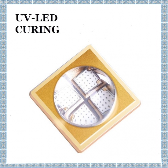
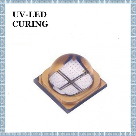
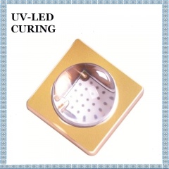
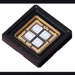
LG Four Chips 365nm UV LED Light Beads is encapsulated quartz glass lens, with newly developed ultra-high quartz glass lens + ceramic packaging technology.
model no. :
15W Four Chips UV LED LightBrand:
LGport of dispatch :
SHENZHENPayment :
T/T 100% Before Shipmentoriginal region :
CHINALG Four Chips 365nm UV LED Light Beads is encapsulated quartz glass lens. In the encapsulation technology, the lamp bead encapsulated with four chips is not suitable for silicone lens, which is easy to be yellow and fall off, and the light fades quickly.
LG UV LED Curing LED Chip, Newly developed ultra-high quartz glass lens + ceramic packaging technology, small angle light design, packaging size of 7070, silicon-based UV LED emitting high purity purple light, high current resistance, low thermal resistance, etc.
Suitable for : electronic offset printing (adhesive curing), ceramic and metal painting glazing, fiber drawing, printing, ink printing and other curing application market.
Product Feature :
Ceramic substrate seal
ESD protective
Support Surface Mount Technology (SMT)
Size : 7.0*7.0 mm
Typical Optical Power :
385nm 4200mW @1500mA
395nm 4400mW @1500mA
( Maximum allowable working current : IF max= :2000mA )
Chip type : 55 mil silicon vertical LED chip
Send light angle : 68°
Application :
banknote inspection, mosquito control, manicure, industrial curing
Characteristic Parameters : (T solder pad = 25 ℃)
|
Characteristic |
Symbol |
Minimum Value |
Typical Value |
Maximum Value |
Unit |
Test Condition |
|
Optical Power (385) |
∮e |
4000 |
4200 |
5000 |
mW |
IF=1500mA & 25 ℃ |
|
Optical Power (395) |
∮e |
4000 |
4400 |
5000 |
mW |
|
|
Forward Voltage |
VF |
3 |
- |
3.8 |
V |
|
|
Direct Current |
IF |
- |
1500 |
2000 |
mA |
|
|
Backward Voltage |
VR |
|
|
5 |
V |
|
|
Wavelength |
WLR |
365 |
|
405 |
nm |
|
|
Irradiation Angle |
2θ1/2 |
- |
68 |
- |
° |
|
|
Thermal Resistance |
|
|
2.5 |
|
℃ / W |
|
|
HBM |
ESD |
|
8000 |
|
V |
|
|
T j (Junction Temperature) |
T j |
|
|
125 |
℃ |
Note :
1.When the lamp bead is normally lit, the maximum allowable current is IFMAX = 200mA
2.The lamp bead test data is obtained by UV integrating ball test in cold pulse mode.
3.For lamp bead module products, the maximum temperature TC of PCB board shall not exceed 90℃. (protect chip junction temperature T j≤125℃)
4.The recommended current of this product is IF=500mA, mainly used for curing class light mode for customers.
Optical Power Parameter : (T solder pad = 25 ℃)
|
Wavelength |
Wavelength Range |
Optical Power |
Test Condition |
||
|
Minimum |
Maximum |
Grading |
Optical Power mW |
||
|
UV Wavelength |
380 |
405 |
KM |
4000-5000 |
IF=1500Ma & 25 ℃ |
Note : optical power test error : ±8%
Product coding rules :
VG-P5-KM-TD
Example : the rank of peak wavelength is P5. It means that the peak wavelength range is 380-385nm.
Voltage Step :
|
Rank |
Minimum |
Maximum |
Test Condition |
|
TD |
6.5 |
7.5 |
T solder pad = 25 ℃ |
Step Size :
1. Peak wavelength grading
|
Rank |
Minimum |
Maximum |
Test Condition |
|
P1 |
400 |
405 |
T solder pad = 25 ℃ IF = 1000mA |
|
P2 |
395 |
400 |
|
|
P3 |
390 |
395 |
|
|
P4 |
385 |
390 |
|
|
P5 |
380 |
385 |
Note : peak wavelength test error : ±1.5nm.
2. Optical Power Grading
|
Rank |
Minimum |
Maximum |
Test Condition |
|
KM |
4000 |
5000 |
T solder pad = 25 ℃ IF = 1000mA |
Note : Luminance test error : ±8%.


Precautions for use
How to store Korea LG UV LED ?
1. The product should be stored in an environment with a dry, relative humidity of less than 30% and a storage temperature of 5 to 30 °C.
2. Avoid external damage to the vacuum bag to prevent the bag from leaking and getting wet.
3. Pay attention to moisture. If it is damp, put the patch reel in a 60 °C oven for 24 hours; remove the tape from the bag, preferably within 12 hours
4. LED lights that have been unsealed from the original packaging but have not been soldered should be stored in one of the following ways:
a. After opening, the LED lights can be resealed in the original vacuum bag.
b. Store the parts in a sturdy metal container with a tight lid attached. Place the fresh desiccant and humidity card in a container and check that the relative humidity is less than 30%.
c. Store the parts in a dry, nitrogen-purified cabinet or container and require the cabinet or container to effectively maintain the relative humidity below 30%.
d. After reopening, the reflow soldering is completed within 24 hours. The workshop condition is ≤30°C/60%RH.
e. If there is no environment with a relative humidity below 30% for storage, one hour before reflow, it must be baked.
5. When stacking PCBs or components that contain LEDs, do not drop all weight on the lens. The force applied to the lens can cause the lens to fall off.
A clearance of at least 2 cm should be left above the LED lens, and the foamed wrapping paper should not be used directly on the lamp. The force from the foamed packaging can damage the LED
reflow soldering conditions
1. The printed circuit board should be prepared or cleaned in accordance with the manufacturer's specifications before the LEDs can be placed or soldered onto the PCB.
2. Our company's LEDs are designed to be soldered to the PCB by reflow soldering. Reflow soldering can be done in a reflow oven or by placing the PCB on a hot plate and
following the reflow profile.
3. Pay attention to the reflow conditions when using, and reflow soldering after debugging the reflow temperature. Reflow conditions: preheating temperature 100 ~ 150 ℃; reflow
soldering temperature of 230 ~ 260 ℃, the welding time of 10 seconds.Operators should take electrostatic protection measures and all equipment must be grounded reliably.
4. Reflow soldering should not exceed 2 times at most.
5. Do not apply pressure to the lamp bead when passing the lamp.
6. After the lamp is over, the PCB board cannot be packaged immediately. The PCB board and the lamp bead should be naturally cooled.
Cleaning
after reflow soldering 1. After soldering, the lamp bead should be cooled to room temperature for further processing. Premature handling of the device, especially around the lens, can result in product damage.
2. It is recommended to check the weld consistency. After avoiding the selected parts of the board, the welding process should be able to achieve complete look at reflux (no clear
significant weld particles). From the back of the package and board, there should be almost no holes visible in the soldered area.
3. When cleaning the PCB after soldering, use isopropyl alcohol to clean the PCB. Do not use ultrasonic cleaning. Do not use water to clean PCB boards that have been fitted with lamp beads.
4. Do not use the following chemicals for cleaning: chemicals that
may cause outgassing of aromatic hydrocarbon compounds (eg toluene, xylene)
a. methyl acetate or ethyl acetate (ie: nail polish cleaner)
b. cyanoacrylate Ester (ie:
superglue ) c. Ethylene glycol (including Radio Shack® precision electronic cleaner)
d.PLIOBOND® adhesive
1. High Intensity UV LED Chip has anti-static requirements, and appropriate anti-static measures should be taken during installation and use.
2. Pay attention to the arrangement of the external lines of various devices to prevent the polarity from being wrong. The device must not be too close to the heating element and the operating conditions should not exceed the specified limits.
3. When deciding to install in the hole, calculate the hole size and tolerance of the hole on the board to avoid excessive pressure on the board.
4. Avoid subjecting the LED to any vibration and external forces.
Operating conditions
1. In order for the LED to operate under stable conditions, a series of protective resistors must be connected in series, and the resistance value can be measured by the supply voltage or current of the LED. LED work
for the voltage and current given by a variety of product specifications requirements LED.
2. The circuit must be designed to prevent overvoltage (or overcurrent) that can occur during LED switching. Short current or pulse current can damage the LED connections.
3. When the Fiber Drawing UV Curing UV Light LED light source is working, the ambient temperature will affect its life reliability. Please keep away from the heat source while working, and the surface temperature should be controlled within 60 °C
4. Incompatible volatile organic compounds in the LED-based solid-state lighting design. , may weaken the performance of the illumination system, shorten its
life, so avoid the use of organic compounds in the design and operation.
Other matters
1. This product is a silicone package and cannot be extruded with a hard object.
2. All equipment that touches the LED must be grounded. Operators must wear grounded anti-static gloves, anti-static shoes and anti-static clothing.
 High Power 365nm UV LED Light Beads UV LED Chip
High Power 365nm UV LED Light Beads is used for UV curing, fluorescent spectroscopy, sensors and monitors, phototherapy, printing, coating, etc..
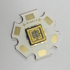 NICHIA NC4U133A NC4U133B 12W 365nm Ultraviolet Bead Four Chip Series Packaging
High Power 12W NICHIA UV Light Beads curing UV ink, UV glue, etc.
 LG 70mW 278nm UVC LED UV Disinfection Lamp
High power 70mW UVC LED UV Disinfection Lamp for water treatment air purification, for laboratory test.
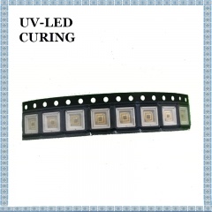
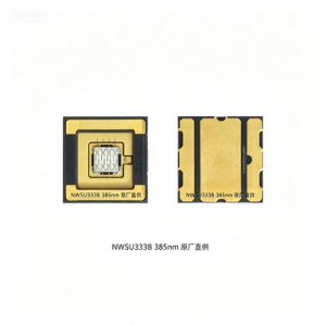
 NICHIA NWSU333B 365nm UV LED Lamp Beads Curing Light Source
NWSU333B LED UV Lamp Source is widely used in UV LED Curing Machine, because of its stable output, high uniformity, and save 80% electrical energy than mercury lamp and low energy consumption.
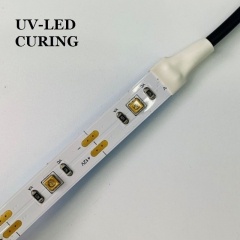 Flexible 270nm UVC LED Sterilization Lamp for Disinfection
Deep Ultraviolet UVA+UVC lamp belt application field : pet environment, medical equipment, house disinfection, pharmaceutical manufacturing, laboratory
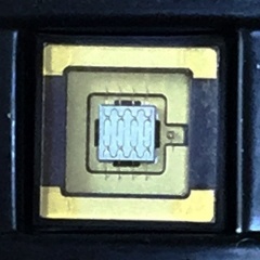
 High Power 4in1 UV LED LG 5w 365nm Ultraviolet Light Bead
365nm 6868 4in1 LED UV Ink Curing Light Chips is used in UV curing, UV ink curing, photo-catalyst, sensor light, etc.
Guangdong Spacelight Technology Co., Ltd.
Tel :
0086-18924372460Fax :
0086-0755-27289230Email :
uvcure@uvspacelight.comSkype :
live:1651063690jenniferWhatsapp :
+8618924372460


Copyright Guangdong Spacelight Technology Co., Ltd.

 English
 français
 Deutsch
 русский
 italiano
 español
 Nederlands
 العربية
 български
 svenska
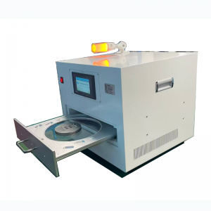
 +8618924372460
 live:1651063690jennifer
 uvcure@uvspacelight.com
 0086-18924372460