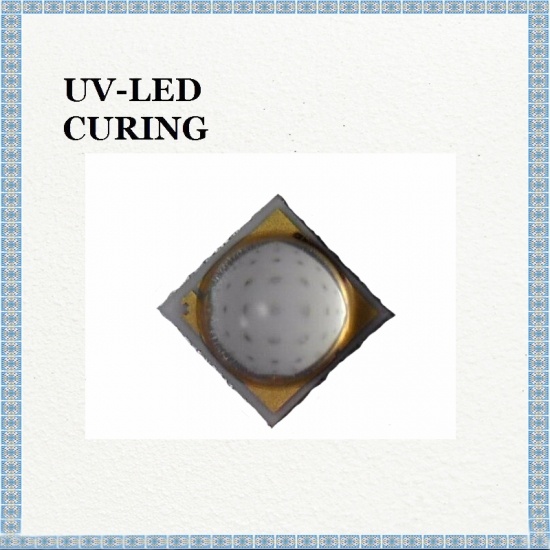
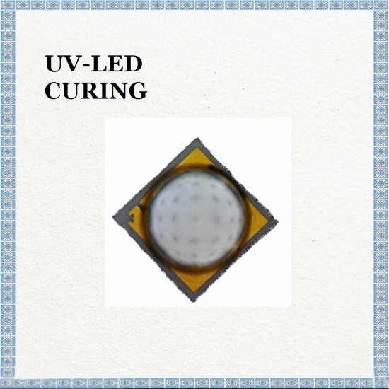
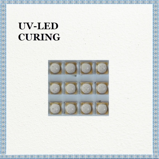
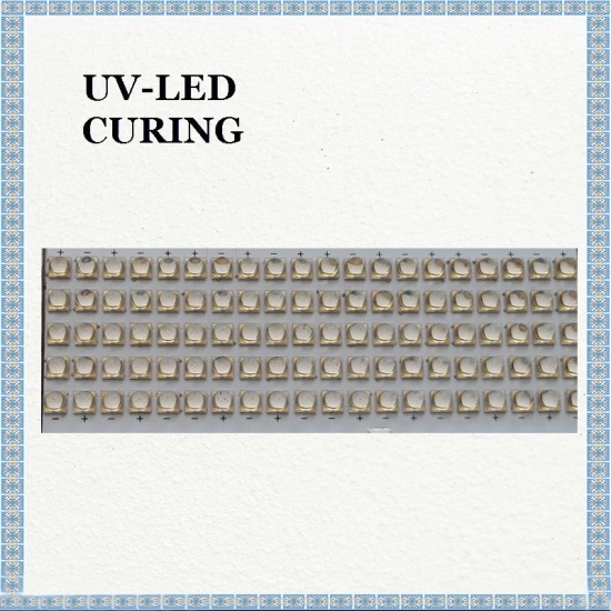
High Power UV LED 395nm Viewing Angle(Directivity): typical 55° , specialized in UV Ink Curing, large printing press, UV LED of rotary press curing light source.
model no. :
395nm UV LED 3W 1300mWBrand:
LGport of dispatch :
SHENZHENPayment :
T/Toriginal region :
CHINALead Time :
The Same DayThe applications of 395nm UV LED 3W 1300mW Used for UV Printing Coating UV Torch are UV Curing, UV Ink Curing, Photo-Catalyst, Sensor Light, etc..
Features
- Surface Mount Type : 3.40×3.40×3.34 (L×W×H, Unit : mm)
- Viewing Angle(Directivity) : Typical 55°
- Soldering Methods : Pb-Free IR-Reflow Soldering
Outline Dimensions

Absolute Maximum Ratings

Electro-Optical Characteristics

Bin Structures

※ Forward Current = 500mA
※ Rank name method : Please refer to the following example
Rank Name : U1-HP12-V2
- Peak Wavelength = U1
- Radiant Flux = HP12
- Forward Voltage = V2
Reliability Test Items and Conditions
1. Failure Criteria

2. Reliability Test

Cautions on Use
2. During Storage

-. The LEDs should be stored in clean environment. If the LEDs are stored for 3 months or more after being shipped from LGIT, a sealed container with a nitrogen gas should be used for storage.
-. When storing the LEDs after opening aluminum bag, reseal with a moisture absorbent material inside
3. During Usage
-. The LED should avoid direct contact with hazardous materials such as sulfur, chlorine, phthalate, etc.
-. The metal parts on the LED can rust when exposed to corrosive gases. Therefore, exposure to corrosive gases must be avoided during operation and storage.
-. The silver-plated metal parts also can be affected not only by the corrosive gases emitted inside of the end-products but by the gases penetrated from outside environment.
-. Extreme environments such as sudden ambient temperature changes or high humidity that can cause condensation must be avoided.
4. Cleaning
-. Do not use brushes for cleaning or organic solvents (i.e. Acetone, TCE, etc..) for washing as they may damage the resin of the LEDs.
-. Isopropyl Alcohol(IPA) is the recommended solvent for cleaning the LEDs under the following
conditions. Cleaning Condition : IPA, 25℃ max. × 60sec max.
-. Ultrasonic cleaning is not recommended.
-. Pretests should be conducted with the actual cleaning process to validate that the process will not damage the LEDs.
6. Static Electricity
-. Wristbands and anti-electrostatic gloves are strongly recommended and all devices, equipment and machinery must be properly grounded when handling the LEDs, which are sensitive against static electricity and surge.
-. Precautions are to be taken against surge voltage to the equipment that mounts the LEDs.
-. Unusual characteristics such as significant increase of current leakage, decrease of turn-on voltage, or non-operation at a low current can occur when the LED is damaged.
8. Recommended Circuit
-. The current through each LED must not exceed the absolute maximum rating when designing the circuits.
-. In general, there can be various forward voltages for LEDs. Different forward voltages in parallel via a single resistor can result in different forward currents to each LED, which also can output different luminous flux values. In the worst case, the currents can exceed the absolute maximum ratings which can stress the LEDs. Matrix circuit with a single resistor for each LED is recommended to avoid the luminous flux fluctuations.

-. The driving circuits must be designed to operate the LEDs by forward bias only.
-. Reverse voltages can damage the zener diode, which can cause the LED to fail.
-. A constant current LED driver is recommended to power the LEDs.
9. Soldering Conditions

10. Soldering Iron
-. The recommended condition is less than 5 seconds at 260℃.
-. The time must be shorter for higher temperatures. (+10℃ → -1sec).
-. The power dissipation of the soldering iron should be lower than 15W and the surface temperature of the device should be controlled at or under 230℃.
11. Eye Safety Guidelines
-. Do not directly look at the light when the LEDs are on.
-. Proceed with caution to avoid the risk of damage to the eyes when examining the LEDs with optical instruments.
12. Manual Handling

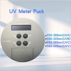 UV Meter Puck Testing UVA UVB UVC UVV Illumination Power Detector
UV Meter Puck can measure four UV wavelength values through the same UV process. The default wavelength is UVA (320-395nm), UVB (280-320nm), UVC (250-260nm), UVV (395-445nm).
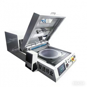
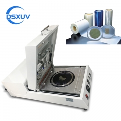 DSXUV-Wafer-M8 8 Inches Manual UV Tape Wafer Mounter
Wafer Frame Film Mounter is a machine that fixes a wafer and a ring together through a blue film or UV film.
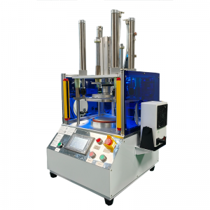
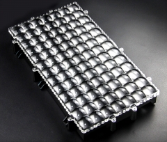 13.3 inches Array 405nm Parallel UV LED Curing Light for LCD Resin 3D Printing
Parallel 405nm UV Light Source Module Lens is widely used in the field of 3D printing
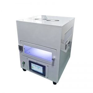
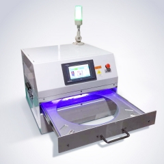
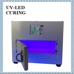 385nm UV Oven Closed UV Curing Box 3D Printing Curing
385nm UV Oven is for 3D printing curing. Closed UV Curing Box do not leak light and is used imported 385nm UV LED Light Beads.
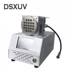 80mm Uniform Light 365nm Circular UV Curing Systems Ultraviolet Surface Light Source
Circle LED UV Solidifying Equipment is simple, easy to maintain. Normal temperature curing, suitable for plastic work-piece, do not produce thermal deformation.
Guangdong Spacelight Technology Co., Ltd.
Tel :
0086-18924372460Fax :
0086-0755-27289230Email :
uvcure@uvspacelight.comSkype :
live:1651063690jenniferWhatsapp :
+8618924372460


Copyright Guangdong Spacelight Technology Co., Ltd.

 English
 français
 Deutsch
 русский
 italiano
 español
 Nederlands
 العربية
 български
 svenska
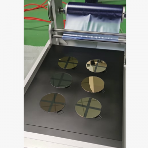

 +8618924372460
 live:1651063690jennifer
 uvcure@uvspacelight.com
 0086-18924372460