2018-03-16
Abstract
UV LED Light Source, compared with the traditional UV light source, has the advantages of environmental protection, low power consumption and band selection. The application of UV LED in printing industry always has many challenges, its reliability issue is particularly acute. The organic materials have the properties of poor UV resistance and high permeability, which the deterioration of its performance will greatly reduce the reliability of UV LED. Based on CMH packing technology, inorganic High Efficiency UV-LED for UV Printing is 100% used inorganic materials packing, with good air tightness, high reliability, long life and low thermal resistance. Because the model of COB and DOB are different of encapsulated material and manufacturing technique, there is a big difference between the performance and reliability of the two. The thermal resistance of the insulation layer of the substrate has a great proportion to the total thermal resistance of COB, and the thermal resistance of the welding interlayer has great influence on the DOB.
Ⅰ、Introduction
In the 1860s, the first UV curing ink appeared. With the rapid development of UV curing technology, the printing industry such as digital printing, stencil printing, plate printing, adagio printing and gravure printing, etc., has been widely used UV curing inks, matching of the UV curing light sources in the traditional light source such as ultraviolet mercury lamp. However, the traditional UV Light source has been restricted by more and more countries because of environmental protection, which makes the market of Ultra-Violet Light Emitting Diode (UV-LED) grow rapidly.
Compared with traditional UV Light Source, UV LED has many advantages such as energy saving and environmental protection, lifetime, low power consumption and optional wavelength. According to the wavelength of the light, UV LED is divided into UVA (315~400NM), UVB (280~315NM), UVC (200~280NM). Generally speaking, greater than 300nm of luminescent wavelength is near UV, less than 300nm of luminescent wavelength is deep UV. According to the different of packing and integration level, UV LED is divided into discrete part and integration mode. In this part, integration mode is divided into COB (Chip On Board) and DOB (Device On Board). However, COB is solder directly on a substrate with a number of LED chip, while DOB is the first to encapsulate the LED chip in the device and then weld multiple devices onto a substrate.
As new product, UV LED also has all kinds of challenges in printing industry. Organic material is exposed to UV energy to produce photo-degradation. Excessive exposure of UV Curing Ink leads to have a perfect mastery of the surface of ink, or insufficient exposure of UV Curing Ink is in poor adhesive property. Harmful substances penetrate UV curing light source and cause the light source to fail. As well as other challenges are matching of UV Curing Light Source and UV Curing Ink, UV Curing Light Source uniformity of light emission, lifetime, stability, reliability of UV Curing Light Source. Nowadays, different LED packing company has different technique. So the type, the quality and the price of UV LED Light Source is diverse, that makes suppliers or consumers suffer the loss because application client is often caused by various reliability problems. Therefore, the article is studied and discussed UV LED discrete part and UV LED integration mode in reliability of printing industry application.

Ⅱ、UV LED Discrete Part
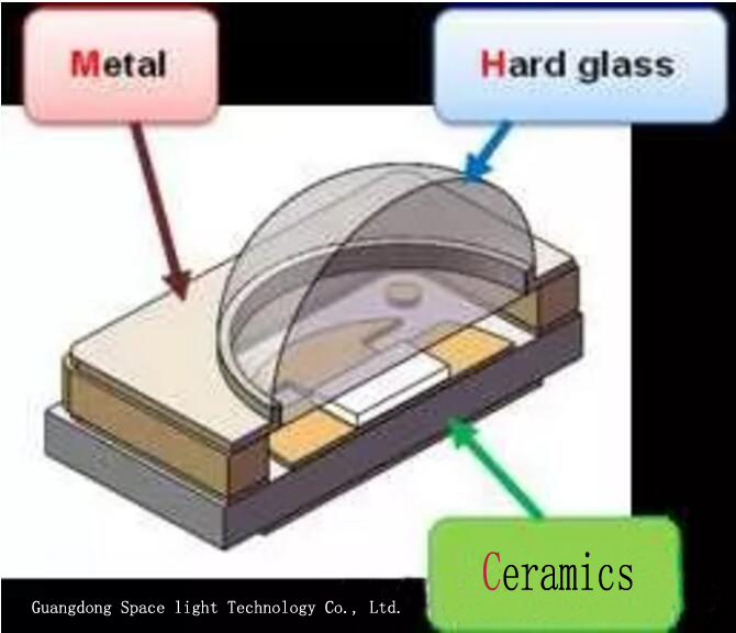
According to different encapsulated material, UV LED discrete part is divided into organic material packing UV LED and inorganic material packing UV LED. Organic material packing UV LED is still used visible light LED device packing. UV LED chip will be coated organic encapsulated material, like epoxy resin, organic silicone, etc.. On the other hand, the product will use organic material as light cup of UV LED device, like EMC series of products in the market. However, inorganic material packing UV LED has improved, aim at ceramics as light up, glass or metal glass as cover plate. In the material properties, the organic material and inorganic material have the big difference. Both are used in UV LED packing. But for properties, lifetime and reliability of the whole device has big difference in influence. In order to facilitate the discussion, organic materials are represented by organic silica gel, and the inorganic materials are represented by glass, and the two are compared in the following aspects.
(1)Transmittance
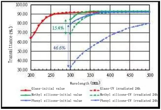
The transmittance of the encapsulated material on the optical path of the chip directly affects the optical output of the UV LED. The higher the transmittance of the material in the UV band, the higher the UV LED light output. Due to the different material properties, the transmittance of different materials in the same UV band can be very different. As we can see, the initial transmittance of organic silicone (methyl silicone and phenyl silicone) has no advantage over glass at all wavelengths of the ultraviolet band. But also, with the decrease of wavelength, the initial penetration rate of organic silica gel and glass will decrease to a different degree. Compared with glass, the initial penetration rate of organic materials will decline much faster than that of glass. When 300nm, the initial penetration rate of methyl silicone is less than 85%, which has a great influence on the optical output of the chip, so methyl silicone is not suitable for the lower ultraviolet band of the band. Otherwise, exposed to 365nm High Efficiency NICHIA UV Light for UV Flashlight 24 hours later, the penetration rate of organic silica gel in the UV band has decreased significantly, while the penetration rate of glass has not changed. It can be seen that, in ultraviolet band, the initial transmittance of glass and the transmittance of UV aging are better than that of organic silicone.
(2)Thermal Properties
For the UV LED of organic materials, the organic materials are not only exposed to ultraviolet light from the chip, but also affected by the heat generated by the chip. Especially organic material of the direct coating on the surface of the chip, high quantity of heat in the form of heat transfer on the surface of the chip directly to organic materials result in for a long time in high temperature working condition. High temperature will accelerate organic material thermal aging. If the organic material of heat-resisting performance is poor, it will appear easily yellowing phenomenon, serious can appear even carbide (black) or cracking and other anomalies. If the device is under a state of switch or high and low temperature cycle for a long time, because of the chip with organic material Thermal Expansion Coefficient (CTE, Coefficient of Thermal Expansion) do not match, chips and organic material of the stick is easy to produce abnormal stripping. Anomalies such as yellowing and peeling can reduce the optical output and reliability of the device.
In order to investigate the thermal performance of organic materials and inorganic materials, methyl silicone, phenyl silicone and glass at the same time in the 260 ℃ oven for baking. Appearance inspection found that the phenyl silicone found on the third day of the baking yellowing, methyl silicone baking in the seventh day though found no obvious etiolation but appeared crack abnormalities, and glass without any apparent anomaly. The yellowing of phenyl silica gel is due to the oxidation of the phenyl of its branched chain in high temperature and oxygen environment, while the cracking of methyl silica gel is due to the high temperature leading to the broken bond. Because the main component of glass is silicon dioxide, its chemical stability is excellent. It can be seen that compared with organic silica gel, the heat resistance of glass has a very large advantage.
(3)Reliability
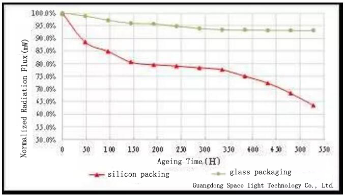
Researching finding, organic material for a long time will happen under UV irradiation light degradation (aerobic environment distributed light oxidation), appear aging and yellowing phenomenon, serious and even cracking. It makes a significant decline in photosynthetic efficiency and reliability of the device, and eventually lead to failure, this phenomenon is particularly serious in deep ultraviolet band. In order to evaluate the reliability level of UV LED or the Anti-UV performance of encapsulated materials, a series of reliability tests are usually carried out. In the normal temperature aging test, under the condition of in the environment temperature, at the same time lighting up UV LED light band at 395nm (chip) of the glass encapsulation and methyl silicone encapsulation, a radiation flux and appearance observation per 48 h.
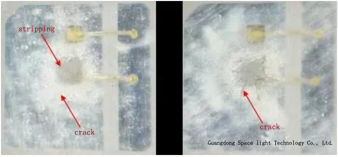
The radiant flux of glass encapsulated UV LED gradually decreased with the increase of aging time, and the radiation flux at 528H was about 93.1% before aging, and no obvious change in appearance. But methyl silicone encapsulated UV LED of radiation flux was to start at the beginning of the aging slash, and did not find any obvious anomaly in appearance. The main reason is that falling transmittance and aging characteristic of methyl silicone (initial radiation fluxes decreased rapidly aging). With the increase of aging time, the lower rate of radiation flux became smaller, the appearance test found that silica gel inside cracks have appeared (mainly distributed near a chip), and silica gel and chip bonding interface has appeared. The appearance of methyl silicone crack indicates that the broken bond has occurred, and the stripping anomaly is due to the mismatch of the thermal expansion coefficient of the silica gel and the chip. At the beginning of aging 336H, the decrease rate of the radiation flux of the UV LED encapsulated by methyl silicone was significantly increased, and the radiation flux at 528H was about 63.4% before the aging. At this time, the appearance test found that the silica gel on the top of the chip had obviously cracked, which is the main reason for the accelerated decline of radiant flux. If the lifetime of the UV LED is defined as the time when the radiation flux drops to 70% of the initial value, then the life of the UV LED sealed by the silica gel is much shorter than that of the glass encapsulated 365nm UV Light Emitting Diode Sell Offers.
(4)Air Tightness
The air tightness of UV LED device is subject to the penetration oxygen rate and the packaging process level of the packaging materials. The encapsulation material has a high penetration oxygen rate, and the air tightness of the device is poor, and the harmful substances in the external environment can easily penetrate the inside of the device and cause the device to fail. The air tightness of the device can lead to various reliability problems, such as chip corrosion and silver plating.
Organic encapsulation material moisture permeability is higher than the glass in the air, for example, methyl silicone oxygen transmission rate is typically 20000 ~ 30000 cm3 / m2 * 24 h * (ATM), phenyl silicone generally is 300 ~ 3000 cm3 / m2 * 24 h * (ATM). Gas and water can penetrate the organic silica gel inside. However, glass is a high density inorganic matter, and its intermolecular gap is smaller than water, so gas and water can't penetrate glass. As a result, glass is easier to encapsulate than organic silicone.
(5) Electrical Property
Organic materials such as organosilicone usually contain a certain amount of Na+, K+ and Cl- plasma, and organic materials are released with small molecules in more or less time. Organic material coating on the chip surface, the material inside the ion or excessive release of small molecules can cause a certain degree of damage to chip's performance, such as chip and reverse leakage current increase. But glass doesn't show this anomaly.
To sum up, the properties of inorganic materials are superior to organic materials. Organic material often match near ultraviolet band High Efficiency UV LED Lights for UV Flashlight to the performance and reliability of occasions with low requirements, and in harsh environments such as high humidity or other occasions with higher requirements of inorganic material for UV LED should be used.
|
Item |
Parameter |
Item |
Parameter |
Item |
Parameter |
|
Wavelength |
265~420nm |
ESD |
≥8000V |
Angle |
45°/60°/120° |
|
Voltage |
3.0~16.0V |
Power |
3~24W |
Lifetime |
≥20000H |
|
Radiation Flux |
1.3~10W |
Dass Tightness |
1*10-8 Pa.m3/S |
Thermal Resistance |
1-6℃/W |
Ⅲ、UV LED Integration Modules
As mentioned above, the common UV LED integration modules on the market are mainly COB and DOB. The differences between the two modules are mainly reflected in the following aspects: 1, packaging materials; 2, production process; 3, light performance; 4, electrical performance; 5, thermal performance.
(1)Packaging Materials
The main difference between COB and DOB in packaging materials is chip and substrate. The COB of the crosswise structure chip and the COB of the vertical structure chip are common in the market, while the DOB uses the vertical structure chip. There are two main types of substrate for UV LED integrated module, copper substrate and AlN ceramic substrate. The difference between the two kinds of substrate is reflected in the following aspects :
1.Price. Aluminum nitride ceramic substrate is more expensive than copper substrate.
2.Structure. The structure of the copper substrate is generally the circuit layer (copper layer), the insulation layer (BT resin) and the copper layer, while the aluminum nitride ceramic substrate is generally the circuit layer and the ceramic layer.
3.Mechanical properties. Aluminum nitride ceramics are brittle and can crack or crack easily during manufacturing and installation, and copper substrate generally does not.
4.Thermal performance. Although the thermal conductivity of copper is higher than that of aluminum nitride, the copper substrate contains a layer of insulating layer, which can hinder the heat dissipation of the chip to some extent.
5.Design diversity. Compared with ceramic substrate, the copper substrate is easier to change in shape and size.
The selection of packaging materials is different, and the performance and reliability of the device are different.
(2)Production Process
It is mainly reflected in the following two aspects:
1.COB generally belongs to customized products, and it is difficult to achieve standardization or mass production, while DOB is attached to the substrate by UV LED devices that have standardized and large-scale production.
2.The manufacturing process of COB is more difficult than DOB. Once the manufacturing defect occurs, such as the collapse line, the whole COB will be scrapped, while the DOB will only lose one device.
Moreover, in the process of use, the COB can only replace the whole light source once the light source fails, and the DOB only needs to replace the failed device.
(3)Light Performance
Because the horizontal structure chip usually uses sapphire as the substrate, its heat dissipation performance is worse than that of the vertical structure chip. Therefore, the maximum forward current and optical power density that the vertical structure chip can be allowed to pass are larger than that of the transverse structure chip. The COB of the transverse structure UV LED chip is often used for low power (below dozens of watts) due to its chip characteristics.
(4)Electrical Performance
At present, the antistatic protection of Best UV LED for UV Flashlight is mainly realized by the way of adding zener. As a result, COB can't do the anti-static protection of each chip, while DOB can. Therefore, the antistatic performance of COB is much worse than DOB. Moreover, DOB modules can be designed to light test and leak current test of single device through the circuit design of the substrate, which is convenient for failure analysis.
(5)Thermal Performance
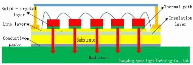
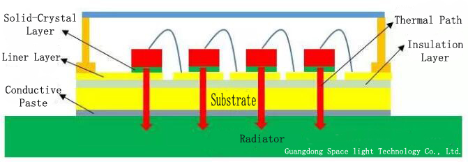
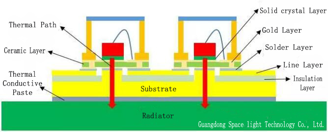
Generally speaking, the heat dissipation path of the UV LED device is mainly three: ① the chip - gold wire - line layer - light cup - environment; ② Chip - outer sealant (gas or air) - lens (cover) - environment; ③ The chip - solid crystal layer - substrate - environment. Path ① and ② is very limited, Path ③ is the main heat dissipation path. Accordingly, the typical structure of COB and DOB and the main cooling path are shown. As mentioned above, the heat dissipation performance of the transverse structure chip itself is not good. So, compared with vertical structure UV LED chip COB and DOB cooling path can be found that DOB on the device more than two very thin layer of gold plated layer and a layer of aluminum nitride ceramics as well as between substrate and device a solder layer, but less in the substrate a layer of insulation. The thermal resistance calculation of COB and DOB is carried out in the ideal state without considering the thermal resistance of diffusion. Compared with DOB, the total thermal resistance of COB is much larger, because the thermal resistance of the insulation layer in COB copper substrate is too large. For DOB, its welding interconnection layer (including solid crystal layer and solder paste, etc.) of the total thermal resistance of relatively large, if the poor welding quality of interconnects, such as insufficient solder or empty a lot, its influence on the total thermal resistance will be greater.
(To be continued, please reed UV LED Reliability Research (Ⅱ))